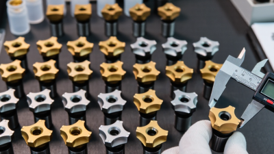
Choosing the right Cnc Insert can determine whether a machining job runs smoothly or becomes an expensive experiment. The decision involves more than matching a shape to a toolholder. Workpiece material, cutting speed, feed rate, depth of cut, coolant, and machine rigidity all influence performance.
Small details matter.
A sharp insert may cut aluminum cleanly, yet fail quickly against hardened steel. A tough grade may survive interrupted cuts, but leave a rougher surface than expected. Experienced machinists inspect chip color, edge wear, vibration, and surface finish before changing grades. Those observations often reveal more than a catalog chart.
Machining researcher Dr. Tony Schmitz emphasizes, “The process is the product.” That idea fits insert selection well. The insert is only one part of a wider cutting system. Tool geometry, workholding, spindle condition, and programming must work together.
This guide presents seven practical tips for buying the right Cnc Insert. It considers insert shape, grade, coating, chipbreaker design, and application data. It also examines supplier support and total operating cost, not only the purchase price. A cheaper insert can become costly when it causes frequent changes, scrap parts, or unstable production.
There is no perfect choice.
Even experienced buyers sometimes select an insert that looks suitable but performs poorly in real conditions. Testing remains important. Start with recommended parameters, record the results, and adjust carefully. That disciplined approach helps turn technical specifications into reliable machining decisions.

7 Tips for Buying the Right CNC Insert
Classify the workpiece using ISO 513 material groups before comparing insert shapes or prices. P represents steel, while M covers stainless steel and its difficult chip control. K includes cast iron, often producing abrasive dust and interrupted cutting loads. N covers non-ferrous metals such as aluminum, copper, and brass. S includes heat-resistant alloys and titanium, where heat remains concentrated near the cutting edge. H refers to hardened steel, usually requiring a wear-resistant edge and controlled cutting conditions.
Check the actual material condition, not only its family label. A soft steel bar and hardened steel component need different insert grades and edge preparations. I once selected an insert based on the material name alone. The result was poor tool life. The overlooked detail was a hardened surface layer. That mistake still influences my purchasing checks. Ask for hardness, tensile condition, casting quality, and whether the cut is continuous or interrupted.
Choose geometry according to chip formation and machine stability. A sharp edge may cut aluminum cleanly, but it can fail during unstable stainless steel machining. A stronger edge may survive interrupted cast iron cuts, although it can increase cutting force. Review recommended speed, feed, and depth ranges from reliable technical data. Then confirm them with a controlled trial. Watch the chips, edge wear, vibration, and finished surface. Small changes matter. Do not buy large quantities before checking performance on your own machine.
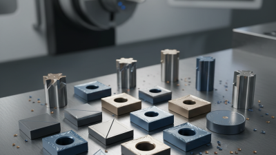
Buying the right CNC insert starts with reading its ISO 1832 designation, not guessing from appearance. The first letter identifies the shape: C commonly means an 80-degree diamond, while D, V, T, and S indicate different cutting geometries. Shape affects accessibility, strength, and the number of usable corners.
The second letter shows the relief angle. An N insert has zero relief, while C and P provide greater clearance for reducing rubbing. More relief can help with tight profiling, but it may weaken the cutting edge. I once selected excessive relief for a roughing operation. The edge chipped sooner than expected.
Look at the remaining characters carefully. They describe tolerance, insert type, size, thickness, and nose radius. A larger radius improves surface finish and edge strength, but it can increase cutting forces. A small radius suits detail work and thin walls. Chipbreaker markings deserve equal attention. They control chip flow for roughing, finishing, or medium cuts, though exact codes can vary by insert system. Check the current ISO table and the supplier’s technical data before ordering.
Keep the workpiece material, feed, depth of cut, and machine rigidity together. A finishing chipbreaker may fail in interrupted cutting. A strong roughing geometry may leave a poor surface. Measure the actual insert pocket, too. Standard-looking dimensions can still expose a costly mismatch. I still recheck the code against the drawing before releasing a purchase order. Tiny letters matter.
| Tip | ISO 1832 Feature | What the Code Tells You | Selection Guidance | Typical Example |
|---|---|---|---|---|
| 1. Match the insert shape to the operation | First letter | The first character identifies the insert shape and included cutting angle. | Use strong, large-angle shapes for roughing and interrupted cuts. Use smaller included angles when access, profiling, or reduced cutting forces are more important. |
C = 80° diamond, a common general-purpose turning shape. D = 55° diamond, useful for profiling. V = 35° diamond, suitable for fine profiling but less robust. S = square, strong edges for heavy work. R = round, high edge strength and favorable chip flow in suitable cuts. |
| 2. Check the relief angle before buying | Second letter | The second character specifies the nominal clearance or relief angle behind the cutting edge. | Negative inserts with 0° relief generally provide strong, often double-sided cutting edges. Positive-relief inserts reduce cutting forces and are useful for small-diameter parts, thin walls, and lower-power machines. |
N = 0° relief. A = 3° relief. B = 5° relief. C = 7° relief. D = 15° relief. P = 11° relief. |
| 3. Confirm holder and insert compatibility | Third and fourth characters | The third character identifies the ISO tolerance class. The fourth character identifies the insert type, including hole, clamping, countersink, and related geometry. | Do not select an insert by shape alone. The insert seat, clamping method, hole design, and chipbreaker clearance must match the toolholder and the machine setup. The exact meaning of some type letters should be verified against the applicable ISO 1832 dimensional table or insert drawing. | In CNMG 120408, M is the tolerance class and G identifies the insert type used in that designation family. The complete holder and insert drawing should be checked before ordering. |
| 4. Choose the correct size for stability | Size code after the four letters | The size portion generally relates to the inscribed-circle size and, depending on the insert shape, is used with the standard dimensional tables to establish the insert’s cutting geometry. | Larger inserts usually offer greater edge support and clamping stability, but they require more workpiece clearance and machine power. Choose the largest insert that fits the holder, workpiece, and tool access requirements. | In CNMG 120408, 12 corresponds to an approximately 12.7 mm inscribed circle for this standard size family. |
| 5. Select thickness according to cutting load | Thickness code | The thickness value is normally encoded after the size designation and is interpreted using the relevant ISO insert dimensions. | Thicker inserts are generally better suited to heavy roughing, high depths of cut, and interrupted machining. Thinner inserts can improve clearance and reduce cutting load but may have less resistance to fracture. | In CNMG 120408, 04 identifies a thickness of approximately 4.76 mm in the common ISO size convention. |
| 6. Match the chipbreaker to feed and depth of cut | Chipbreaker or geometry designation | Chipbreaker geometry is frequently shown as an additional suffix or manufacturer-specific grade and geometry code. It is not fully described by the basic four-letter ISO shape and clearance code alone. | Fine-finishing chipbreakers are intended for lower feeds and lighter depths of cut. Medium geometries cover general turning. Roughing geometries need sufficient chip space and edge strength for higher feeds and depths of cut. Always compare the manufacturer’s chipbreaker range with the material group and cutting data. | A finishing geometry may be appropriate around f = 0.05–0.20 mm/rev, while a roughing geometry may be selected for substantially higher feed rates, provided the insert, machine, workholding, and material support the load. These are starting ranges, not universal limits. |
| 7. Choose nose radius for finish and edge strength | Final two digits | The final two digits identify the nose-radius size in the ISO designation convention. | A larger radius improves edge strength and can support higher feeds, but it increases cutting forces and may cause vibration on slender workpieces. A smaller radius lowers cutting force and improves access but is more vulnerable to chipping. |
In CNMG 120408, 08 indicates an approximately 0.8 mm nose radius. For a theoretical turning-finish estimate, Ra ≈ f²/(32r), using consistent units; actual roughness also depends on tool condition, material, vibration, machine accuracy, and chip control. |
| Designation | Code Segment | Interpretation | Approximate Common Dimension |
|---|---|---|---|
| CNMG 120408 | C | 80° diamond shape | Included angle: 80° |
| N | Neutral clearance | 0° relief | |
| M | ISO tolerance class | Verify limits in the applicable ISO table | |
| G | Insert type and hole/clamping configuration | Confirm with the insert drawing and holder specification | |
| 12 | Nominal size code | Approximately 12.7 mm inscribed circle | |
| 04 | Thickness code | Approximately 4.76 mm thickness | |
| 08 | Nose-radius code | Approximately 0.8 mm radius |
Choose the carbide grade from the workpiece, not from habit. ISO 3685 recommends testing tool life under controlled cutting conditions, including speed, feed, depth, and failure criteria. Start with the supplier’s speed range, then run a short trial at three speeds. Keep feed and depth constant. Small changes matter.
Watch the chip color, crater wear, and flank-wear width. Shiny wear land. Wrong grade. Use a tougher substrate for interrupted cuts, and a harder grade for stable, continuous cutting. Select coating chemistry for heat, adhesion, and abrasion. Industry cutting-tool benchmark reports also show that tool cost is only a small part of machining cost; downtime and replacement labor often dominate. I still check the chips twice. Charts can mislead when clamping, coolant, or runout is unstable. Record actual parts per edge, not just minutes of cutting.
7 Tips for Buying the Right CNC Insert
Set Speed, Feed, and Depth of Cut with Taylor’s Equation: VT^n = C
Choosing a CNC insert starts with the workpiece, machine rigidity, and cutting conditions. A hard alloy needs different edge strength than a soft aluminum grade. Insert shape also matters. A sharp edge reduces cutting force, while a stronger edge handles interrupted cuts better.
Taylor’s equation, VT^n = C, links cutting speed with tool life. V means cutting speed, T means expected tool life, and n describes the insert material. C comes from controlled tests or reliable technical data. If you need longer tool life, reduce speed using V = C/T^n. A small speed change can create a large life difference. That surprises many operators.
Feed and depth of cut are not direct terms in the basic equation. However, both change heat, cutting force, and insert wear. Start with a moderate feed and a stable depth of cut. Watch the chip color, sound, and flank wear after a short trial. A blue chip may signal excessive heat. A rubbing sound may indicate insufficient feed.
The first estimate is rarely perfect. Machine power, coolant delivery, workholding, and material variation can shift the result. Keep notes for each trial. Record speed, feed, depth, tool life, and wear pattern. Then adjust one variable at a time. This method feels slower, but it prevents costly guesses.
This chart illustrates how cutting speed affects expected tool life using Taylor’s equation, V × Tn = C. The example uses n = 0.25 and C = 300, with speed measured in metres per minute and tool life in minutes. Actual values vary with insert grade, workpiece material, feed, depth of cut, coolant, and machine conditions.
Buying takeaway: Choose an insert grade that supports the required cutting speed while balancing wear resistance, toughness, feed rate, and depth-of-cut capability. A small increase in cutting speed can produce a significant reduction in tool life.
A reliable insert decision starts with seven checks:
Confirm the insert’s shape, thickness, corner radius, and holder match before comparing prices. A small mismatch can create vibration, poor seating, or sudden edge failure. ISO 13399 data helps standardize insert dimensions and reduces ordering errors.
Coolant deserves more attention than it usually receives.
Check pressure, flow direction, concentration, and thermal shock resistance. A 2019 CIRP review reported that cutting fluids can represent 7–17% of machining costs, while cutting tools may represent only 2–4%.
Cheap inserts can become expensive when they demand higher coolant use or cause frequent stoppages. The U.S. Department of Energy also identifies fluid management as a practical efficiency opportunity in industrial plants.
Run a controlled trial before approving volume purchases.
Keep spindle speed, feed, depth of cut, material batch, and coolant settings consistent. Record tool life, surface roughness, burr formation, chip shape, and cost per component.
I once judged an insert only by minutes of tool life. That was incomplete. It produced longer chips and needed manual clearing.
Trial results should include operator handling and machine stability, not only cutting time. Reject unclear claims, even when the price looks attractive.