Choosing a CNC mist collector starts with understanding what your machines release, not with comparing catalog prices. Cnc Mist can include fine oil droplets, water-based coolant, or a changing mix of both. Each behaves differently inside an enclosure and places different demands on filters. A unit that works well beside one lathe may struggle with several machines running at once.
Look closely at the process. Note the coolant type, machine cycle, enclosure openings, and visible mist around doors or vents. These details help determine the required airflow and where extraction should connect. Too little airflow can leave mist hanging near the operator. Too much can waste energy or pull useful coolant from the work area. Small details matter.
Filter design is only part of the decision. Ask how the collector handles coarse droplets, fine aerosols, and oil drainage. Check filter replacement intervals, access for cleaning, noise ratings, and the pressure drop as filters load. A clear maintenance plan often matters more than a polished brochure. It is easy to overlook.
This guide explains how to compare collector types, estimate system needs, and review installation constraints before choosing equipment. It also covers practical questions to ask suppliers, such as tested airflow under real filter conditions and compatibility with your coolant. No single specification guarantees a good result. Actual performance depends on the machine, layout, and upkeep, so confirm recommendations against site conditions and manufacturer data. Even a careful selection may need adjustment after installation. That is worth admitting.
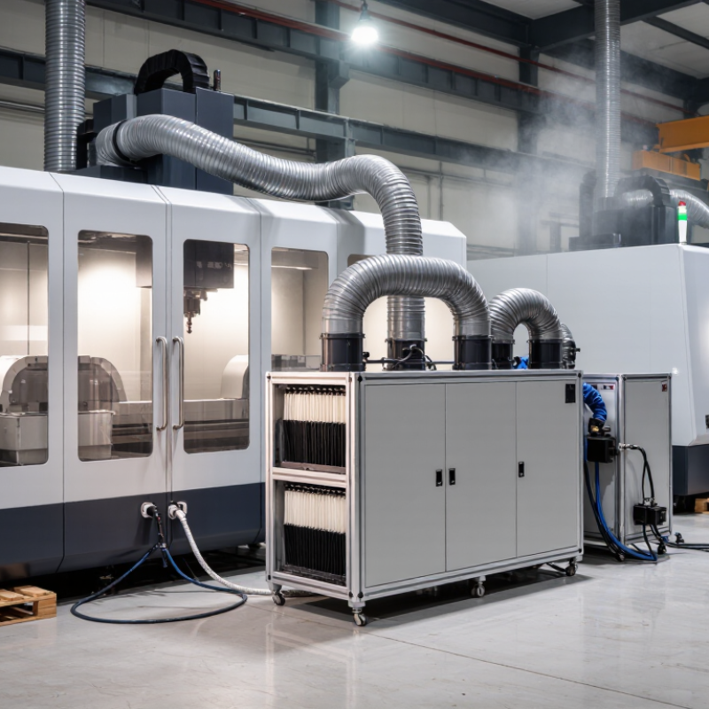
Before choosing a collector, identify what is airborne and where it forms. A pale cloud near the spindle may be coolant mist, but appearance alone can mislead. Water-miscible coolant often creates fine droplets during high-speed cutting or when coolant strikes a rotating tool. Neat cutting oil can produce a heavier, persistent aerosol that leaves a slick film on nearby surfaces. Very fine particles from dry machining are different from liquid mist and may need separate assessment.
Observe the machine during a full cycle, including tool changes and door opening. Note when the plume appears, how far it travels, and whether it settles as wet residue. Short bursts near the tool enclosure may point to cutting or coolant delivery; steady haze can suggest leakage, poor containment, or mist escaping through openings. Check the coolant type and safety data, and ask operators about changes in fluid, tooling, or cycle speed. A brief smell is not a reliable test.
Also distinguish mist from smoke-like aerosol caused by heated lubricant. It may look similar, yet its source and control needs can differ. Do not assume one machine has only one emission type. Mixed fluids, worn seals, and compressed-air blowoff can complicate the picture. A simple observation log is useful, though it will not replace a qualified exposure assessment when visibility is poor or workers report irritation.

Assess each CNC machine before comparing collector capacity. Record whether it is enclosed, the size of its access openings, coolant type, spindle speed, and cutting cycle. A sealed machining center that stays closed during cutting behaves differently from an open lathe with frequent operator access. Note when doors open, too: mist can escape during loading, even if the collector performs well during machining.
Production patterns matter just as much. Count machines likely to run at the same time, and note shifts, peak workloads, and coolant changes. High-pressure coolant, fine droplets, and long continuous cuts can increase the mist burden. Check the machine maker’s extraction guidance, then verify airflow at the actual connection and inspect for leaks. A tidy duct layout helps. It is not proof of capture.
Use exposure data as a design reference, not a substitute for site measurements. NIOSH’s Criteria for a Recommended Standard: Occupational Exposure to Metalworking Fluids (1998) recommends limits of 0.4 mg/m³ for thoracic particulate and 0.5 mg/m³ for total particulate, averaged over a work shift. These figures concern worker exposure, not collector sizing. Still, they show why a machine-by-machine assessment matters. A rough production estimate can miss door-opening releases and changing workloads. Measure and reassess after installation.
CNC mist collectors use different methods, and the best fit depends on coolant, airflow, and maintenance needs. Centrifugal units spin droplets out of the airstream; they suit heavier, readily separated mist. Coalescing filters capture fine droplets on layered media, where they merge and drain. Electrostatic collectors charge and attract airborne particles, but dirty plates can reduce performance. Check the drain.
Filtration stages matter as much as the collection method. A washable pre-filter can catch larger droplets and chips, while finer media handles residual mist. Look for documented airflow and efficiency at the particle sizes relevant to your process, not just a headline rating. NIOSH’s 1998 Criteria for a Recommended Standard: Occupational Exposure to Metalworking Fluids recommends limits of 0.4 mg/m³ for thoracic particulate and 0.5 mg/m³ for total particulate, as time-weighted averages. These are exposure benchmarks, not guarantees of collector performance.
Match the system to the fluid: neat oil may behave differently from water-based coolant, especially when temperatures rise or tramp oil is present. Ask how often filters need service, where collected liquid drains, and whether performance has been tested under similar conditions. A clean-looking unit can still leak mist. A neat specification sheet can mislead, too; real results depend on installation, airflow balance, and upkeep.
Choosing the collector capacity starts with the mist source, not the room size. Check the machine enclosure, coolant type, and expected operating hours. A fully enclosed CNC machine usually needs less airflow than an open cutting area. Use the machine’s airflow recommendations when available, then account for duct length, bends, and the number of machines running at once. These details affect resistance in the system. Small ducts can quietly reduce performance.
Leave room for real conditions. A filter may load with oil over time, and doors may stay open during setup. I have seen neat airflow estimates miss these ordinary changes. Allow a sensible capacity margin, but avoid oversizing without reason; excess airflow can waste energy and disturb nearby work areas. Place the collector close to the machine when practical. Keep duct runs short and smooth, and avoid sharp bends. Keep service panels accessible, with enough clearance to remove filters and inspect drains. Check that discharged air will not blow mist toward operators or other equipment. It is easy to overlook the return airflow. Test the setup while the machine is cutting, then adjust if mist escapes around the enclosure.
A CNC mist collector should match the machine, coolant, and actual production hours. Check the required airflow at each enclosure, not just the collector’s headline rating. A narrow duct, clogged pre-filter, or poorly placed pickup can reduce capture. Watch for mist settling on the machine window or forming a slick film nearby. Small details matter.
Maintenance affects both uptime and cost. Ask how often filters need inspection, cleaning, or replacement under similar operating conditions. Coolant type, shift length, and chip load can change service intervals. Check whether filters are easy to reach and whether collected liquid can drain back safely. A difficult filter change may be postponed. That is a real operating cost, even if it never appears on the quote.
Safety needs practical attention. Confirm that the unit suits the expected aerosol and works with the machine enclosure and ventilation plan. Operators should be able to spot leaks, unusual noise, or rising filter pressure without opening a running unit. Compare purchase price with energy use, replacement filters, labor, and downtime over several years. Cheap can become expensive. Still, estimates are imperfect; use your own maintenance records and coolant conditions to refine them.
| System or Decision Factor | Suitable Use | Maintenance Review | Safety and Installation Checks | Operating-Cost Considerations |
|---|---|---|---|---|
| Machine-mounted collector | One CNC machine or a small number of machines with separate enclosures and collection points. | Inspect the inlet, drain, seals, and filter condition at the interval recommended for the unit and process. Check for blocked drains or fluid carryover. | Confirm that the machine enclosure is adequately closed and that airflow does not interfere with machining or draw coolant out of the enclosure. | Consider electricity, replacement filters, disposal, and the time needed to service each unit. Several units may require more individual inspections. |
| Centralized ducted system | Multiple machines where a designed duct network can serve the required collection points. | Inspect filters, ducts, branches, dampers, drains, and the fan. Monitor airflow because changes at one branch can affect other machines. | Have the duct layout and airflow balanced for the machines in use. Review discharge location, access for cleaning, and applicable fire and building requirements. | Include fan electricity, duct installation, filter replacement, and balancing or service work. Energy use depends on fan power and operating hours. |
| Mechanical filtration | Applications where droplets can be captured by staged filters or coalescing media selected for the fluid and aerosol. | Check pressure drop and follow the filter maker’s cleaning or replacement instructions. A loaded filter can reduce airflow and increase fan energy. | Verify that the selected media is compatible with the coolant or oil and that collected liquid drains and is handled appropriately. | Compare filter life, replacement cost, disposal requirements, and the energy impact of pressure drop—not just the initial equipment price. |
| Electrostatic precipitation | Some fine-oil-mist applications, where the system is specifically selected for the process and maintained as instructed. | Collector cells require regular inspection and cleaning; residue buildup can reduce performance. Follow electrical isolation procedures before service. | Review the equipment’s electrical safety instructions and suitability for the fluid, aerosol, and installation environment. Do not assume it is appropriate for every process. | Account for electricity, cell-cleaning labor, cleaning supplies, and any required downtime. Actual costs depend on contamination rate and service frequency. |
| Fluid and process compatibility | All systems; selection should reflect whether the process produces oil mist, water-miscible coolant mist, or a changing mixture. | Ask how the fluid’s concentration, additives, and contamination affect filter loading, drainage, and cleaning intervals. | Consult the fluid safety data sheet and the collector documentation. Assess exposure controls and applicable workplace requirements for the specific fluid and operation. | Different fluids can change filter life, maintenance labor, waste handling, and the amount of recovered liquid. |
| Airflow and capture performance | All systems; size and layout should be based on machine enclosure, collection points, duct losses, and the process. | Use a repeatable inspection or measurement method to identify declining airflow. Check doors, seals, ducts, and filters when performance changes. | Verify capture under actual operating conditions, including machine doors and production cycles. Avoid relying on nominal airflow alone as proof of exposure control. | Undersizing can lead to poor capture; oversizing can waste energy. Compare the required airflow and pressure against the fan’s operating data. |
| Annual electricity estimate | A practical comparison method for any collector type. | Keep fan and operating-hour records; investigate unexpected increases in power use or pressure drop. | Use the equipment nameplate and installation details when estimating electrical demand. Electrical work should follow applicable codes. | Estimated annual energy cost = input power (kW) × operating hours per year × electricity rate per kWh. Use measured input power where available; nameplate motor rating is not necessarily actual average power. |
| Total cost of ownership | Comparing shortlisted systems over a consistent service period. | Include planned filter changes, cleaning labor, inspections, repairs, and downtime. | Include installation, ducting, electrical work, discharge arrangements, and any required safety measures. | Compare purchase and installation cost plus energy, filters, labor, waste handling, and repairs. Request assumptions for service intervals and replacement parts. |
Selection note: No collector type or service interval suits every CNC process. Confirm airflow, fluid compatibility, exposure-control needs, and maintenance requirements with the equipment documentation and applicable local regulations.