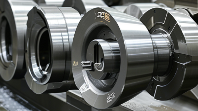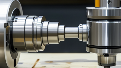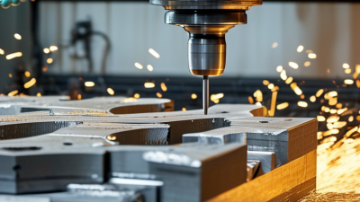
A Cnc Axle is more than a shaped steel shaft. It is a load-bearing component that transfers torque, supports rotating assemblies, and must remain stable under shock, heat, and vibration. OICA reported global motor-vehicle production of about 93.5 million units in 2023. That scale explains the demand for accurate, repeatable axle manufacturing. Yet production volume alone does not guarantee safety or durability.
Peter Smid, author of CNC Programming Handbook, states, “The machine tool does not make the part; the programmer does.” This principle fits Cnc Axle production closely. Engineers begin with load calculations, CAD geometry, material selection, and spline requirements. A CNC lathe then turns the blank, while milling, drilling, broaching, or hobbing creates critical features. Heat treatment follows. It may improve hardness, but poor control can create distortion or hidden cracks.
Small errors matter.
The final axle is checked for diameter, concentricity, runout, surface finish, and spline accuracy. Coordinate-measuring machines and torque tests help verify performance. Grand View Research’s automotive axle market analysis indicates continued growth, driven by commercial vehicles, passenger cars, and changing drivetrain designs. However, market forecasts are not manufacturing guarantees. They can overlook supplier quality, maintenance habits, or real operating conditions.
This article explains what a Cnc Axle is, how manufacturers produce it, and where failures can begin. The process sounds controlled. It is not perfect. Skilled inspection still matters.
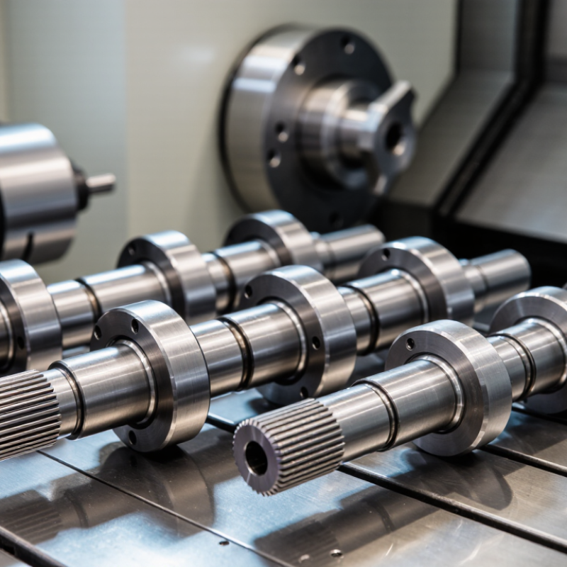
What Is a CNC Axle and How Is It Made?
Definition and Core Functions of a CNC Axle
A CNC axle is a precision-machined shaft that supports rotating wheels or components. It transfers torque while carrying radial and bending loads. Depending on the vehicle or machine, it may include splines, bearing seats, flanges, and threaded sections. The definition is not perfectly universal. Some engineers use “axle” for a complete assembly, while others mean only the central shaft.
Its geometry controls wheel alignment, rotation stability, and load distribution. A poorly machined bearing seat can create vibration, heat, and premature wear. That risk matters in a large production environment. The International Organization of Motor Vehicle Manufacturers reported approximately 93.5 million motor vehicles produced worldwide in 2023. Even a small dimensional error can therefore affect many assemblies.
Manufacturing usually begins with alloy steel bar stock. CNC turning forms the main diameter and shoulders. Milling or broaching creates splines and keyways. Drilling produces accurate bolt or oil passages. Heat treatment improves strength, but excessive hardness can make later grinding difficult. Final inspection commonly uses a coordinate measuring machine, micrometers, and runout gauges. ISO 230-2 provides a recognized method for evaluating machine-tool positioning accuracy. It does not guarantee a perfect axle. Tool wear, clamping pressure, and temperature still influence results. That is the part manufacturers sometimes underestimate. A reliable process records these variables, checks critical surfaces repeatedly, and corrects deviations before assembly.
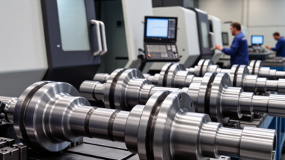
A CNC axle is a machined shaft that transfers torque while supporting rotating parts. Its material choice controls strength, weight, wear, and machining cost. In shop practice, alloy steel remains common because it handles repeated bending and shock loads. A typical steel axle uses a diameter near 25–40 mm, but the correct size depends on torque, span, bearing support, and safety factor.
Aluminum weighs about 2.7 g/cm³, compared with steel at approximately 7.85 g/cm³, according to ASM material data. It can reduce unsprung mass, but its lower stiffness may require a larger diameter. Titanium offers high strength with lower density than steel, although cutting time and tool wear can rise sharply. The U.S. Department of Energy reports that a 10% vehicle weight reduction may improve fuel economy by roughly 6–8%. That figure supports lightweight design, not careless thinning.
Fatigue resistance matters most.
Engineers should model keyways, shoulders, and splines carefully because stress concentrates around sharp transitions. CNC turning creates the basic profile, while milling produces slots or mounting features. Heat treatment can increase hardness, but excessive hardness may reduce toughness. Surface finishing also matters; a rough bearing seat can accelerate wear and vibration. Dimensional inspection should verify runout, diameter, and concentricity using calibrated equipment. I would not trust a polished surface alone. A visually perfect axle can still fail under cyclic torque. SAE and ASTM guidance should support material selection, testing, and traceability throughout production.
A CNC axle begins as a measured digital model, not a block of metal alone. The designer defines shaft diameters, shoulder positions, keyways, and bearing seats in CAD software. Each dimension needs a clear datum and a realistic tolerance. A drawing may show perfect numbers, but manufacturing conditions are never perfectly stable. Heat, tool wear, and clamping pressure can change the final size.
The model then guides CNC program preparation. The programmer selects stock dimensions, workholding methods, cutting tools, spindle speeds, and feed rates. Toolpaths should remove material gradually around shoulders and grooves. Sharp transitions often create stress points or poor surface finishes. I prefer checking these areas twice. Small oversights become expensive after machining begins.
Before cutting, the program is reviewed through simulation. The operator checks tool clearance, axis movement, cutting depth, and the location of the work zero. A dry run can reveal risky movements that software misses. It is not a guarantee. The first program is rarely final. After machining, an inspector measures critical diameters with calibrated instruments and compares them with the drawing. If one seat is slightly oversized, the team should investigate the cause rather than simply adjust the next part. That reflection improves future models, setups, and inspection plans.
What Is a CNC Axle and How Is It Made?
Step-by-Step CNC Axle Manufacturing Process
A CNC axle is a precision-machined shaft that transfers load and rotation between moving parts. Its design begins with a detailed drawing showing diameter, length, bearing seats, keyways, threads, and tolerance limits. Engineers select steel or another suitable alloy according to strength, wear, and operating conditions. Material choice matters.
The machinist cuts round bar slightly longer than the finished axle. The bar is secured in a CNC lathe, and the machine faces both ends before turning the main diameter. Cutting tools then create shoulders, grooves, and bearing journals with controlled feed rates. A live tool may drill cross-holes, mill flats, or produce keyways. Internal or external threads are cut according to the drawing. Coolant reduces heat and helps protect the surface finish.
After machining, the axle is cleaned and measured with micrometers, calipers, and gauges. Critical areas receive extra inspection because a small error can affect alignment or bearing life. Some axles undergo heat treatment, grinding, or protective coating after initial machining. Final checks may include runout measurement, hardness testing, and visual inspection for burrs or tool marks. The process is not flawless. Tool wear, incorrect offsets, or unstable clamping can create defects, so experienced operators verify dimensions during production rather than waiting until the end. In practice, one overlooked setup detail can force a useful part back onto the machine.
| Step | Manufacturing Stage | Main Activities | Typical Inputs or Parameters | Equipment or Tooling | Quality Checks | Expected Output |
|---|---|---|---|---|---|---|
| 1 | Part Definition and Design Review | Define the axle type, load path, bearing seats, splines, keyways, threads, flange features, and datum structure in a 2D drawing or 3D CAD model. | Common shaft diameters: 20–80 mm Typical overall length: 150–1,200 mm Critical tolerance classes identified before machining |
CAD software, engineering drawings, design-for-manufacturing checklist | Material specification, datum scheme, fit requirements, geometric tolerances, and safety factors | Released manufacturing drawing and CNC program requirements |
| 2 | Material Selection and Incoming Inspection | Select a suitable steel or alloy steel bar, forging, or near-net-shape blank according to strength, toughness, wear, and heat-treatment requirements. | Typical axle materials include medium-carbon steel and alloy steel grades Bar diameter selected with machining allowance |
Material certificates, micrometers, calipers, hardness tester, positive material identification equipment | Grade verification, diameter, straightness, surface defects, and traceability | Approved raw blank with documented material identity |
| 3 | Blank Cutting and Preparation | Cut the stock to length, remove burrs, face the ends, and create center marks or pilot features when required for stable machining. | Cut length = finished length plus machining allowance Typical allowance: 2–10 mm per end, depending on the blank and process |
Automatic saw, band saw, cutoff machine, facing tool, deburring tools | Cut length, squareness, burr removal, and visible cracks or laminations | Clean, correctly sized blank ready for turning |
| 4 | CNC Turning: Rough Machining | Establish the primary datum, reduce the outer diameter, form shoulders, and remove most of the excess material while maintaining enough stock for finishing. | Typical roughing depth of cut: 1–4 mm radial Feed and speed selected by material, tool grade, rigidity, and diameter |
CNC lathe, hydraulic or collet chuck, carbide turning inserts, steady rest for long shafts | Diameter checks, runout, shoulder location, tool wear, and chip control | Near-net-shape axle body with consistent machining allowance |
| 5 | CNC Turning: Finish Machining | Finish bearing journals, seal lands, shoulders, tapers, chamfers, and threaded sections to their specified dimensions and surface condition. | Common bearing-seat dimensional tolerance: approximately IT6–IT7 when specified Typical machined surface roughness: Ra 0.8–3.2 μm, depending on feature |
CNC turning center, precision inserts, thread-cutting tools, coolant system, probing system | Micrometer measurements, thread gauges, surface-finish measurement, concentricity and runout checks | Dimensionally finished cylindrical features |
| 6 | CNC Milling of Secondary Features | Machine flats, keyways, cross-drilled holes, bolt patterns, flange faces, reliefs, or other non-rotational features. | Feature position controlled from established datums Hole and slot sizes selected from the engineering drawing |
4-axis or 5-axis machining center, end mills, drills, boring tools, rotary fixture or soft jaws | Feature location, flatness, hole diameter, perpendicularity, slot width, and burr inspection | Axle with accurately positioned secondary features |
| 7 | Spline, Gear, or Serration Production | Create torque-transfer teeth when required using milling, shaping, hobbing, broaching, or cold-forming methods appropriate to the geometry and production volume. | Profile, tooth count, pitch, pressure angle, and fit class specified by the drawing or applicable standard | Spline cutter, gear hobbing machine, broaching machine, or CNC milling center | Tooth profile, major and minor diameters, pitch or over-pins measurement, backlash, and visual damage inspection | Functional torque-transfer profile |
| 8 | Heat Treatment | Apply hardening, tempering, carburizing, induction hardening, or another specified treatment to improve strength, fatigue resistance, or wear performance. | Process depends on steel grade and required case or core properties Tempering is normally used after hardening |
Controlled-atmosphere furnace, induction unit, quench system, tempering furnace | Hardness, case depth when applicable, distortion, cracks, and heat-treatment records | Axle with specified mechanical and wear properties |
| 9 | Post-Treatment Straightening and Finish Grinding | Correct heat-treatment distortion if necessary, then grind bearing seats, seal lands, or other critical surfaces to achieve final size and finish. | Grinding stock commonly kept within a small allowance after heat treatment Final runout may be specified below 0.05 mm for critical journals |
Hydraulic straightening press, cylindrical grinder, centerless grinder, balancing or runout fixture | Journal size, roundness, cylindricity, taper, surface roughness, and total indicated runout | Precision-finished critical surfaces |
| 10 | Deburring, Cleaning, and Surface Protection | Remove sharp edges and machining residue, wash the part, dry it, and apply corrosion protection or a specified coating when required. | Edge break commonly about 0.2–0.8 mm unless otherwise specified Protect precision fits from coating buildup |
Deburring tools, aqueous washer, compressed air, rust preventive, masking materials | Burr-free edges, cleanliness, coating coverage, masking condition, and corrosion protection | Clean and protected axle ready for final inspection |
| 11 | Final Dimensional and Functional Inspection | Verify all critical dimensions, geometric relationships, interfaces, and functional features against the approved drawing and inspection plan. | Typical tools include micrometers, gauges, height gauges, roundness testers, and coordinate measuring machines | Coordinate measuring machine, optical comparator, roundness tester, torque-transfer gauges | Dimensions, datums, runout, concentricity, perpendicularity, hardness, spline fit, and surface finish | Accepted axle with inspection report and traceability record |
| 12 | Packaging and Storage | Apply protective packaging, isolate finished surfaces from impact and moisture, label the part, and store it in a clean, dry area. | Packaging must prevent corrosion, contact damage, contamination, and distortion during handling | Protective sleeves, rust-inhibiting paper or film, separators, labels, storage racks | Part identification, packaging integrity, surface condition, and quantity verification | Shipment-ready CNC axle |
A CNC axle is a precision-machined shaft that transfers rotation, torque, or motion. It may include splines, keyways, shoulders, threads, and bearing seats. Typical production begins with alloy steel, stainless steel, or aluminum bar stock. Turning establishes the main diameter. Milling creates flats or grooves. Grinding improves bearing surfaces. Heat treatment may increase hardness, but it can also cause distortion.
Quality inspection must follow the axle’s function, not just its drawing. Technicians check diameter, concentricity, runout, surface roughness, hardness, and thread accuracy. A coordinate-measuring machine can verify complex profiles. Micrometers and dial indicators remain useful on the shop floor. Material certificates and batch records support traceability. ISO 9001-based systems also require controlled inspection records. Small details matter. A 0.02-millimeter runout can create vibration in a fast rotating assembly.
The International Federation of Robotics reported 541,302 industrial robots installed worldwide in 2023. This demand increases the need for reliable robot joints, drive shafts, and compact axles. CNC axles also serve electric drivetrains, agricultural machinery, conveyors, medical equipment, and automated inspection systems. Manufacturers often apply statistical process control, using Cpk values near 1.33 for stable critical dimensions. That target is not universal. Design risk and service loads still decide acceptance. Inspection is not flawless. A clean report can hide poor cleaning, worn probes, or incorrect datum setup. Experienced inspectors recheck unusual readings before release.
This chart compares the theoretical torsional capacity of a 30 mm solid CNC-machined axle made from three widely used engineering materials. The values are calculated from representative yield strengths using the maximum-shear-stress criterion and do not include a safety factor, keyways, fatigue loading, or stress concentrations.
CNC axles are commonly produced by turning, drilling, milling, threading, and deburring. Quality inspection typically includes dimensional measurement, surface-finish verification, concentricity checks, hardness testing, and visual inspection for burrs, cracks, or machining defects. Typical applications include automotive components, robotics, conveyors, agricultural equipment, and industrial machinery.